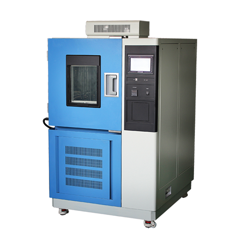
Constant temperature and humidity test chambers are widely used in various fields, including electronics, electrical appliances, mobile phones, instruments, vehicles, plastic products, metals, chemicals, medical applications, and aerospace for quality testing. Many users are not very familiar with the refrigeration pipeline of this equipment. In the previous article, we explained the first major point regarding pipeline issues. Below, we will continue with the remaining two major points:
- For units equipped with condensers and evaporators, users can design and install the cooling water and refrigerant circulation systems according to the technical parameter requirements of the product. However, it is necessary to install a water flow switch in front of the evaporator’s inlet pipe to provide water cutoff protection for the evaporator. This ensures sufficient flow, and valves should be installed in the water circuits of the condenser and evaporator to facilitate flow regulation.
For ease of operation and observation, temperature gauges and pressure gauges should first be installed at the water inlet and outlet of the condenser and the refrigerant inlet and outlet of the evaporator. After the water system and refrigerant system pipelines are installed, they should be pressurized with gas at 1.0 MPa for a leak test. Finally, the refrigerant inlet and outlet pipelines and valves of the evaporator should be wrapped with insulation layers, followed by moisture-proof sealing treatment on the outer layer.
- The electrical wiring connections and requirements for the constant temperature and humidity test chamber should be carried out in accordance with the electrical control user manual.
The above explanation covers the treatment of the refrigeration pipeline for constant temperature and humidity test chambers. We hope this content can provide some assistance to users!